How To We Reach Our Goal
利用Matlab去進行 SIN 和 COS 之波型的模擬並採樣,其中的數值將全部轉換成0與1,之後將結果錄進去.txt 檔之中。 主要流程為:
可以參考以下圖片與程式碼:
sin波:
                % Set parameters
                f1 = 5000; % waveform frequency
                fs = 32 * f1; % sampling frequency, ensuring 32 points per cycle
                N = 12; % number of quantization bits
                num_cycles = 2000; % number of cycles
                samples_per_cycle = 32; % sampling points per cycle

                % Generate time vector
                t = 0:1/fs:(samples_per_cycle * num_cycles - 1)/fs;

                % Generate sine wave
                sin_wave = 2047 * sin(2 * pi * f1 * t);

                % Quantize to 12 bits
                quantized_wave = round(sin_wave);

                % Convert positive and negative values to 12-bit signed values
                % Set values greater than or equal to 2048 to the maximum value
                quantized_wave(quantized_wave >= 2048) = 2047;
                % Set values less than or equal to -2048 to the minimum value
                quantized_wave(quantized_wave <= -2048) = -2048;

                % Convert to 12-bit binary strings
                binary_wave = dec2bin(quantized_wave + 2048, N);

                % Write to text file
                fid = fopen('C:\homework\Communication experiment\project\testdata_sin', 'w');
                for i = 1:length(binary_wave)
                    fprintf(fid, '%s\n', binary_wave(i, :));
                end
                fclose(fid);
cos波:
                    % Set parameters
                    f1 = 5000; % waveform frequency
                    fs = 32 * f1; % sampling frequency, ensuring 32 points per cycle
                    N = 12; % number of quantization bits
                    num_cycles = 2000; % number of cycles
                    samples_per_cycle = 32; % sampling points per cycle

                    % Generate time vector
                    t = 0:1/fs:(samples_per_cycle * num_cycles - 1)/fs;

                    % Generate cos wave
                    cos_wave = 2047 * cos(2 * pi * f1 * t);

                    % Quantize to 12 bits
                    quantized_wave = round(cos_wave);

                    % Convert positive and negative values to 12-bit signed values
                    % Set values greater than or equal to 2048 to the maximum value
                    quantized_wave(quantized_wave >= 2048) = 2047;
                    % Set values less than or equal to -2048 to the minimum value
                    quantized_wave(quantized_wave <= -2048) = -2048;

                    % Convert to 12-bit binary strings
                    binary_wave = dec2bin(quantized_wave + 2048, N);

                    % Write to text file
                    fid = fopen('C:\homework\Communication experiment\project\testdata_cos', 'w');
                    for i = 1:length(binary_wave)
                        fprintf(fid, '%s\n', binary_wave(i, :));
                    end
                    fclose(fid);
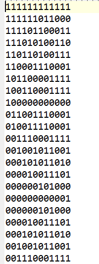
波形之二進字
利用Verilog撰寫PSK的模塊,可以分成兩部分,分別為調變與解調:
程式碼如下:
                        // PSK Modulation
                        always @(posedge clk_1M or negedge rst) begin
                        if (!rst) begin
                            Mod_out0 <= 0;
                            Mod_out1 <= 0;
                        end else begin
                            if (M_out == 1'b0)
                            Mod_out0 <= cos0;
                            else
                            Mod_out1 <= sin1;
                        end
                        end
程式碼如下:
                    // PSK Demodulation
                    always @(posedge clk_1M or negedge rst) begin
                      if (!rst)
                        demod_out <= 0;
                      else if (received_signal == cos0)
                        demod_out <= 1'b0;
                      else if (received_signal == sin1)
                        demod_out <= 1'b1;
                    end
用於生成相位增量。每個時鐘週期增加固定的相位增量,輸出作為查找表的地址。
利用M-ary產生器,所產生的信號,可以分成兩個部分。
第一部分為clk_div,其通過計數來實現時鐘分頻,當計數達到設定的最大值 Max 時,
輸出時鐘信號 clk_div 翻轉一次。
這樣,輸出時鐘的頻率會是輸入時鐘的頻率除以 (Max+1)。
程式碼如下:
                    clk_div #(
                        .Max (500)  // 設定參數 Max 的值為 500
                    ) u3 (
                        .clk(clk),  // 輸入時鐘信號
                        .rst(rst),  // 輸入重置信號
                        .clk_div(clk_M)  // 輸出分頻後的時鐘信號
                    );
第二部分為M_gen 模塊,其是一個多相序列生成器,通常用於生成偽隨機序列。
這些序列在數字通信、加密和測試中廣泛應用。
M 序列(Maximum Length Sequence)是由線性反饋移位寄存器 (LFSR) 生成的,
具有最大周期性且擁有良好的統計特性。
程式碼如下:
                    M_gen #(
                    .width (8)  // 設定參數 width 的值為 8
                    ) u4 (
                    .clk(clk_M),  // 輸入分頻後的時鐘信號
                    .rst(rst),    // 輸入重置信號
                    .M_out(M_out)  // 輸出 M 序列信號
                    );
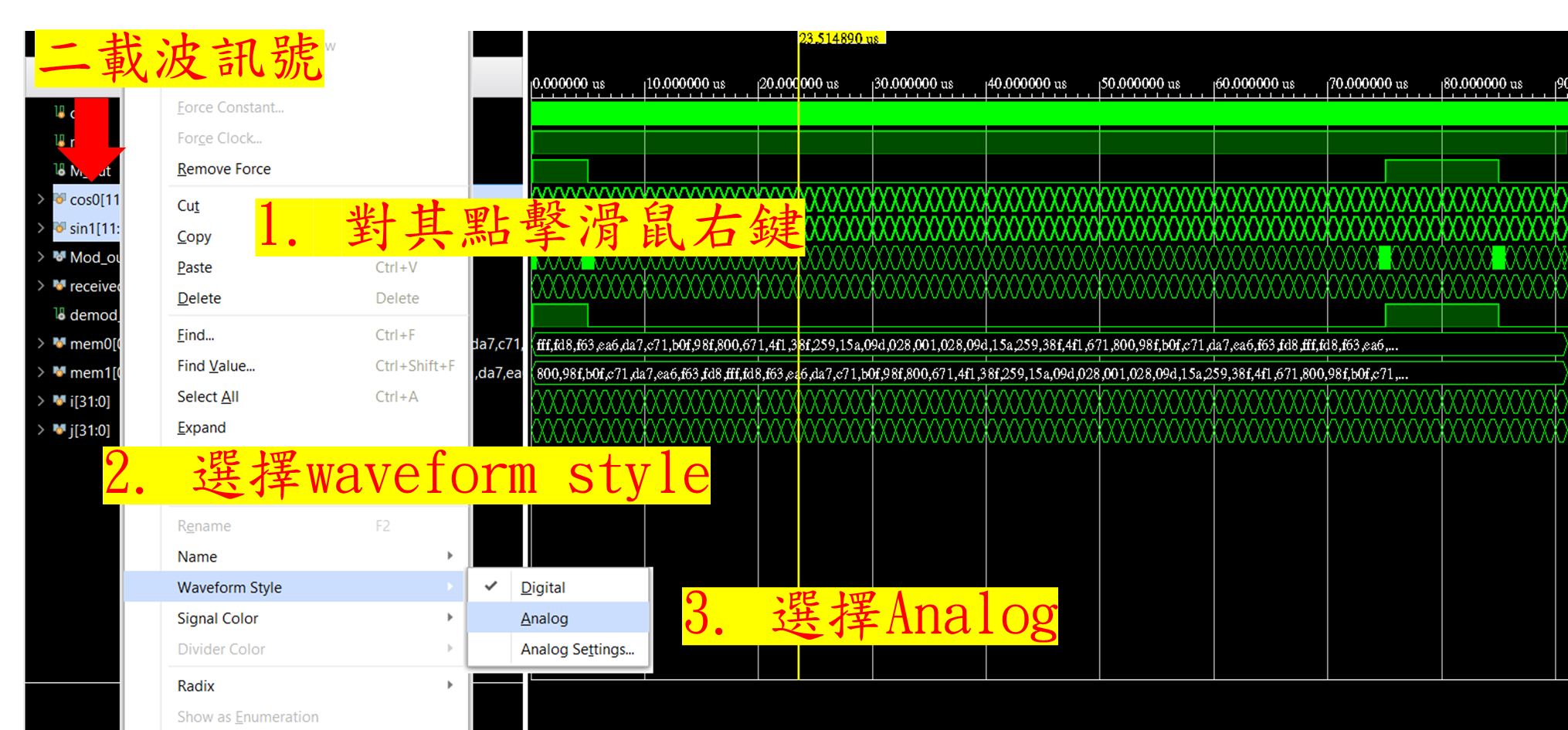
在數位電路設計軟體Vivado 中,輸出模擬圖通常是數位方波圖。
在數位通信中,一些調變方式(如PSK)依賴類比弦波信號作為載波。
因此,能夠在模擬軟體中顯示類比信號是非常重要的。
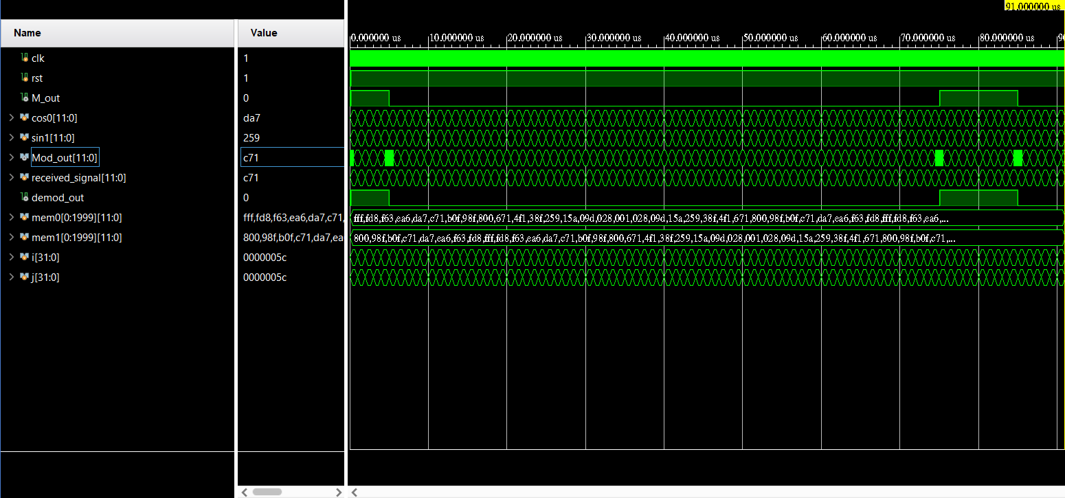
下方為尚未進行DAC轉換之圖片:
在Vivado中,利用wave style來達成類比訊號的轉換,只需該訊號點擊右鍵,如下圖: